In general, MEEP can leverage the FPGA built-in components and hardware macros, and efficiently map other components (IPs or custom designs) to the available structures of the FPGA. The components in the system are arranged as multiple accelerator cores operating in parallel, and able to execute different kinds of HPC applications.
MEEP extends the traditional accelerator system architecture beyond the traditional CPU-GPU systems by presenting a self-hosted accelerator.
This self-hosted accelerator can increase the number of accelerators “managed” by a traditional host, reducing the host CPU energy tax, boosting the system efficiency.
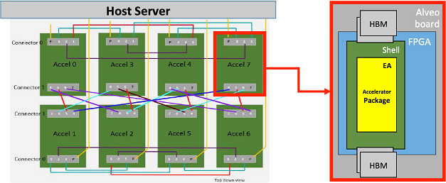
More specifically, the emulation platform architecture might be structured into two well-differentiated parts (below):
- The FPGA Shell: This element contains all the necessary mechanisms for the accelerator to communicate with the host, and also with other neighboring accelerators.
- The Emulated Accelerator (EA): This element is where all the data processing is executed and involves computation and memory management.
Communication infrastructure
As shown above, the host server is connected by PCIe to each of the FPGAs (host interface) and all FPGAs are fully connected with dedicated SerDes (Serializer/Deserializer) links, enabling all-to-all communication between the FPGAs or emulated accelerators.
This communication infrastructure can be exposed to the software layers in a variety of ways, like OpenMP/MPI, etc. Thus, we have software APIs to enable as well as the RTL and IP blocks inside the FPGA to move the bits around. All of these communication options enable a wide variety of EA mappings and system compositions utilizing one or more FPGAs to define a node.
Emulated accelerator architecture
MEEP’s first emulated accelerator architecture is a disaggregated access-execution architecture that allows us to embed more intelligence near the memory controller and, in doing so, select how to use the memory interface.
The key challenge is to combine the knowledge of the larger data structures (vectors), with the application program flow to optimize the use of the on-chip memory hierarchy. Using vectors enables the system to see into the future and orchestrate memory requests in both space and time, providing a glimpse into the future, and optimizing on-chip memory usage.
The emulated accelerator architecture is a scale-down instance of the ACME accelerator, which has the need to communicate with the rest of the system (host, and/or other accelerators in different FPGAs). Here is where the Software Stack and the Hardware Stack come together to provide the required capabilities to the system to be able to run applications.
The following video describes and shows the implemented mechanisms to communicate the current version of the emulated accelerator with the host: Demo.
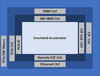
The Shell
Each FPGA in the system will use a standard FPGA shell defined in MEEP, as three distinct layers (below). This FPGA shell is composed of IP blocks common to most FPGA-based systems for communication and access to memory:
- PCIe: This IP allows the communication between the host and the FPGA. It provides a universal interconnect to the chip and the system.
- HBM: This IP provides fast and high memory capacity to promote a self-hosting accelerator.
- F2F: The accelerator links are useful for nearest-neighbor and remote FPGA communication (F2F); inter and intra chiplet data movement.
The innermost concentric ring is the MEEP shell interface to the internal FPGA logic of the emulated accelerator or other FPGA functionality. This ring is MEEP specific RTL that provides a common interface to the remaining FPGA logic. The goal is to keep it as minimal and flexible as possible.
Current work: Emulation platform architecture-Phase 1
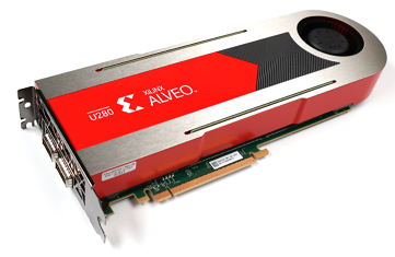
Taking advantage of the latest available FPGA hardware platform, MEEP uses the Alveo U280 [Xilinx-U280], an actively cooled FPGA card, as shown in the figure below. This uses the VU37P FPGA. This FPGA has various hard IP blocks that can be used in the system, including: HBM and related memory controller, PCIe controller and drivers, QSFP and Ethernet functionality. These hard macros align well with some of the base functionality of the ACME EA.
As part of this Phase 1, and having as a final goal the generation of a functional FPGA Shell, the work has been divided into several steps:
(1) characterizing each of the IPs separately: This first step will allow us to understand the requirements and features of each of these IPs and, at the same time, identify the missing pieces that need to be developed in order to fulfil the emulation platform expectations. The following videos shown the progress on them:
- HBM. This is a demonstrator of how by exploiting the reordering features of the HBM the performance can be improved.
- FPGA to FPGA communication through Aurora. The following video shows the communication of two U280 boards with this IP, and details about the implementation.
- FPGA to FPGA communication through Ethernet. The video shows the integration of this IP in OpenPiton, as a first approach to the final MEEP solution, and how two U280 boards are able to communicate through it.
If you prefer to read what has been done with the Ethernet IP, do not forget to take a look at the article: 'MEEP Shell - Part 1: The Ethernet IP.'
(2) the FPGA Shell as a composition of all these individual IPs: The objective pursued by this step is to create an IP with clear and clean interfaces to allow the exploitation of these IPs in a seamless way. In an attempt to create functional flavors of an FPGA Shell, the first approach includes the PCIe and the HBM, which are the minimal required IPs to communicate with the host and with the emulation platform (and the inner EA), and to enable the self-hosting features, respectively.
(3) connecting the EA to the FPGA Shell: Here is where the RTL of the accelerator architecture and the FPGA Shell converge to create an emulated accelerator able to interact with the rest of the system (the host and/or other emulated accelerators).
The following video collects the progress of the steps (2) and (3) together. Actually, a more detailed explanation about what is the MEEP FPGA Shell and its real implementation in the emulation platform is shown. Demo: Automatic Shell + EA generation