MEEP (MareNostrum Experimental Exascale Platform) aims to develop an exploratory supercomputing infrastructure for the development, integration, testing, and co-design of a wide range of European technologies that could form part of future European exascale systems based on European-developed intellectual property. The ultimate goal is to create an open full-stack (software and hardware) ecosystem that could form the foundation for many other European systems, both in HPC and embedded computing, with benefits for numerous stakeholders within academia and industry.
This article offers a walkthrough of one of MEEP's technical goals, which is to provide a self-hosting, flexible, and scalable accelerator. It delves deeply into each accelerator characteristic to then offer a clear system overview so as to better understand how the accelerators and host interconnection interact.
Self-hosting
In the domain of High-Performance Computing (HPC), the speed of data processing programs depends on the number of available compute cores. While MEEP consists of scalar processors such as RISC-V compatible CPUs to execute the OS as well as sequential operations, it also has coprocessors designed for specific workloads exhibiting a high degree of parallelization. Therefore a MEEP processor is not only able to boot and run an operating system, but it is also able to locally execute highly parallel programs, thereby removing the communication bottleneck between a host on which the program is started and the transport of operands and results across to processors specialized in parallel executions such as GPGPUs.
This execution paradigm of an OS running on a normal CPU and the integration of coprocessors ensures that MEEP is a self-hosting accelerator or in other words, it means that the envisioned accelerator behaves like a normal computer.
Scalability
At the same time, the MEEP project builds an accelerator that scales. First, the number of resources that are available within the MEEP accelerator can be adapted and it depends on the area requirement of the target configuration. If an FPGA is the target, the availability of look up tables (LUTs: a basic building block for digital logic), flip flops (FFs: a storage cell), and other FPGA resources determine how many accelerators and scalar processors can be included.
In addition, if higher computational capabilities are required, the MEEP accelerators can be linked together to utilize their resources such as the coprocessors to increase the capacity for parallel data processing.
Flexibility
As a first step, MEEP is to be deployed on Xilinx’ Alveo U280 Data Center Accelerator[1]. It consists of an FPGA with integrated up to 16GB High Bandwidth Memory (HBM)[2], PCIe (Gen 3, 16 lanes) and two Ethernet QSFP28 interfaces, able to deliver 100Gbps each. To access the hardware modules, MEEP utilizes an FPGA Shell as shown in Figure 1, below.
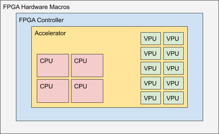
The MEEP FPGA shell has two layers shown in Figure 1, the FPGA Hardware Macros and the FPGA Controller. The outer layer called FPGA Hardware Macros includes the hardware macros that are available on the FPGA. Those are fixed IP blocks that have been implemented by the FPGA vendor and include functionalities such as PCIe, HBM, external DDR memory controllers and Ethernet connectivity.
The next inner layer contains MEEP specific controllers. Those controllers not only manage the hardware macros of the outer layer but also provide interfaces towards the Accelerator, the innermost layer. Those interfaces include memory controllers that can access the on-chip HBM[2] and external DDR memory, Ethernet functionality[3], and FPGA-to-FPGA communication. By bringing the HBM memory close to the computational resources, another bottleneck that is commonly found in HPC applications, is removed: The data transfer rate from and to the main memory. Usually, the memory is located off-chip and hence despite the available computation capabilities, they cannot be fully utilized as the data cannot be moved in and out of the processor fast enough. To ease access from the accelerator to the HBM, the memory controllers have been placed into the FPGA Shell.
The innermost layer is the Accelerator consisting of one or multiple scalar processors and coprocessors specific to the workload under consideration. In figure 1, the coprocessors consist of vector processing units (VPU) and systolic arrays. VPUs are optimized for matrix operations as these operations are commonly found in the HPC domain and the majority of applications will benefit from such an implementation, while systolic arrays accelerate video processing and neural network computations. The coprocessors are organized in modules and by observing the interfaces, modules such as the vector unit or the scalar processor can be replaced or extended.
System Overview
To share resources among MEEP accelerators, a possible constellation consists of multiple accelerators and a host as shown in Figure 2, below.
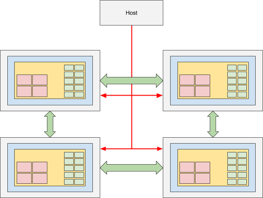
While the accelerators exchange data among themselves using QSFP (green arrows in the figure), the host will communicate via PCIe (in red) with the accelerators. The host orchestrates administrative tasks such as the access to external resources like storage, or the user management. As an example, a user is logged into one of the host and schedules workloads to be executed on the MEEP accelerators. The workload could request data from its own HBM, other accelerators, or through services offered by the host establishing e.g. connectivity to remote network storage. In the latter case, the request for data travels through the PCIe connection and the host forwards that request to e.g. the storage clusters in the data center. The requested data is then streamed back directly to the MEEP accelerator through the host, where the workload is processed by the coprocessors. This setup decouples the MEEP accelerators from the environment ensuring flexibility in the deployment.
References:
- Xilinx, Alveo U280 Data Center Accelerator Card Data Sheet, Sep 2020
- Xilinx, AXI High Bandwidth Memory Controller v1.0 LogiCORE IP Product Guide, Jul 2020
- Xilinx, UltraScale+ Devices Integrated 100G Ethernet Subsystem v2.6 Product Guide, May 2019