The self-hosted accelerator conceived in MEEP is envisioned as a collection of chiplets that are composed together in a module. The goal of MEEP is to capture the essential components of one of the chiplets in the FPGA and replicate that instance multiple times.
Although those components might be seen as a collection of different elements, they can be separated into two main categories according to their main functionality: memory or computation (below).
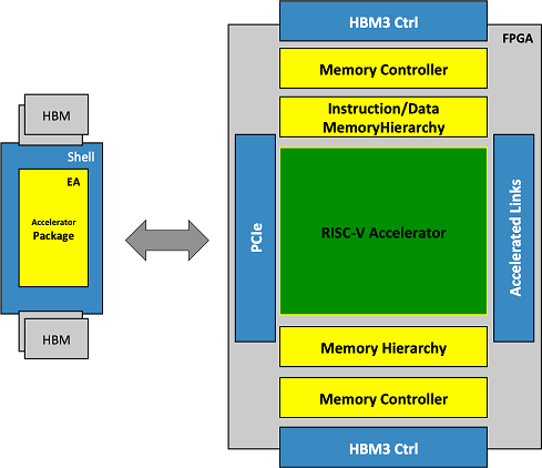
On one hand, all memory components will be distributed creating a complex memory hierarchy (from HBM and the intelligent memory controllers down to the scratchpads, and L1 caches).
On the other hand, the computational components will be organized into hierarchical layers by following a bottom-up approach, starting at module-level and building on top of that by composition, up to a system-level component. This one can be seen as the computational engine, which will be a RISC-V based accelerator.
The targeted accelerator in MEEP is called Accelerated Compute and Memory Engines (ACME), and the figure below shows its high-level architecture view with a variety of different blocks.
The figure below shows the high-level ACME architecture with a variety of different major blocks.
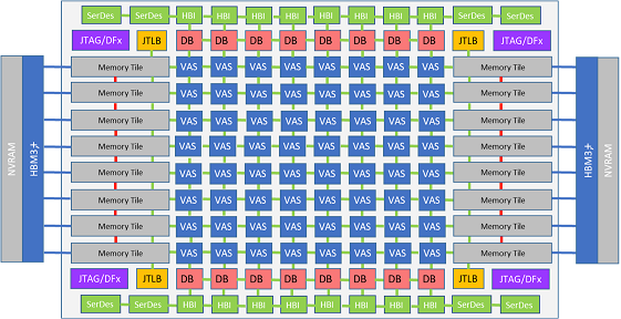
1. ACME Accelerator in MEEP
The ACME accelerator is composed of two main components: (1) the computational engine, and (2) the memory engine. Both of them are in charge of increasing the performance of the accelerator under different working contexts, since they are developed for specific tasks. On one hand, the computational engine is responsible for operating with the data (scalar and vector elements). On the other hand, the memory engine is responsible for dealing with memory transactions and accesses, with the final purpose of reducing the energy and saving memory accesses.
The table below summarizes the main features to be exploited by the architecture under different working contexts, based on the dominant HPC application characteristic.
|
Main Component |
System-level Architecture |
Module-level Micro architecture |
Features |
|
Computational Engine |
matrix of VAS Tiles |
1. Scalar core 2. Co-processors 2.1. VPU, 2.2. SA-HEVC 2.3. SA-NN |
(Compute-bound applications) ●Specialized accelerators (VPU, SA-HEVC, SA-NN) ●Common co-processor shell ●ISA upgrade ●Custom instructions ●New interlane interconnect |
|
Memory Engine |
matrix of Memory Tiles |
1. Two-Level VRF 2. MCPU 3. Flexible L2/L3 4.Memory Controller |
(Memory-bandwidth bound applications) ●Streaming Vector Register File ●Real & Virtualized vector length ●Memory operation off-loading ●Flexible memory hierarchy ●Smart memory addressing ●Sparse to dense transformation ●Smart data management |
According to the table, the Computational Engine is designed to perform well on the compute-bound applications, whereas the Memory Engine is designed to improve the efficiency for memory-bandwidth bound applications.
Accelerated computational engine
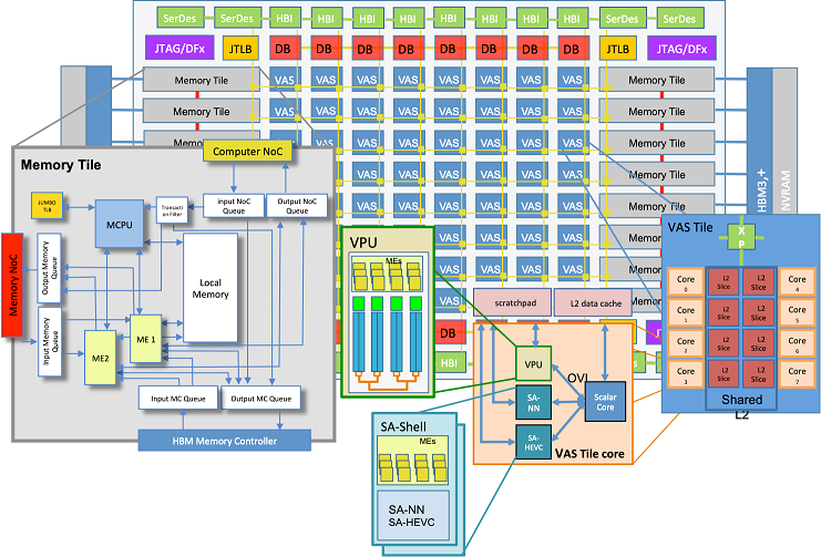
Each VAS Accelerator Tile is designed as a multi-core RISC-V processor, capable of processing both scalar and vector instructions. Going down, each core is a composition of three elements: a scalar core and three coupled co-processors.
- Scalar core: It is a traditional RISC-V scalar processor with the capability of recognizing coprocessor and special instructions, for it (RISC-V vector and systolic array extensions) and resend them to one of its co-processors.
- Co-processors: These units are added to the accelerator design with the aim of accelerating as much as possible the computation and memory operations, but also reducing power consumption and data movements.
- Vector processing unit (VPU): It is a specialized unit able to process RISC-V vector extension instructions.
- Systolic array unit: MEEP implements a systolic array shell or template that provides standard coprocessor and memory interfaces. There are two systolic arrays, 1 for video and image processing and 1 for neural networks.
- Memory Controller CPU (MCPU): It is a specialized unit that can process both scalar and vector memory instructions as well as atomics and simple arithmetic operations. Using vectors, the MCPU can see into the future of large memory requests and manage memory resources to maximize performance and minimize energy. It is placed as close as possible to the main memory controller unit to reduce latencies.

Accelerated Memory Engine
The Memory Engine is formed by a matrix of Memory Tiles, where each of them contains a RISC-V processor playing the role of Memory Controller CPU (MCPU), and some logic to execute memory operations.
The main responsibilities of the Memory Engine are:
- Optimizing the accesses to main memory, by minimizing and reducing the transactions.
- Creating a dense representation of data in case data is not unit-stride in memory (i.e. non-unit stride vectors, indexed vectors {scatter/gather})
- Adding a certain level of intelligence to the system in order to increase data reusability.
- Controlling data movements between Memory Tiles and VAS Tiles.
2. Modelling the ACME accelerator architecture
The targeted ACME accelerator in MEEP has an inherent research nature. That is the reason why the initial assumptions and expected features need to be validated and explored in depth. Additionally, to this, the high-level view of the ACME architecture needs to be refined by defining lower level granularity details (how the components interact among them, bus widths, memory and communication policies, etc.). All these things together contribute to refine the specifications of this accelerator architecture. The way to conduct all these activities is through a performance modeling analysis, which in the final goal is to provide a data-driven decision foundation, according to the analysis of the simulation results.
Coyote as a performance modeling simulator
As an evaluation platform, MEEP has to provide tools to test new ideas in early stages, but also along the development cycle of the target accelerator.
For this reason, MEEP has developed Coyote, a performance modeling tool able to provide an execution driven simulation environment for multicore RISC-V systems with multi-level memory hierarchies.
In this context, MEEP developed Coyote to provide the following performance modeling tool capabilities:
- Support for RISC-V ISA, both scalar and vector instructions.
- Model deep and complex memory hierarchies structures.
- Multicore support
- Simulate high throughput scenarios.
- Leverage with existing tools
- Include scalability, flexibility and extensibility features to be able to adapt to different working context and system characteristics.
- Easy to enable different architectural changes, in order to provide an easy-to-use mechanism to compare new architectural ideas.
Based on these criteria, MEEP found no existing infrastructures to use and created Coyote, a combination of two well-known simulation tools, Sparta and SPIKE. It focuses on modeling data movements throughout the memory hierarchy. This provides sufficient detail to perform:
- First-order comparison between different design points.
- The behaviour of memory accesses.
- The well-known memory-wall.
Being the last two barrier to efficient computing. Cache coherence and lower level modelling of the cores are out of scope for Coyote.
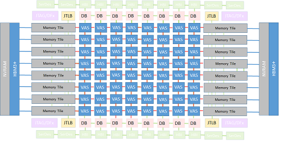
Coyote currently can model an architecture with a private L1 cache (data and instruction) and a shared banked L2 cache. The simulator allows to configure the size and the associativity of the L2 cache, and also the number of in-flight misses and the hit/miss latencies. Regarding the data mapping policies, Coyote supports page to bank (P2B) and set interleaving (SI). These features allow modeling simple tiled systems, including their L2s, implementing different sharing modes and data mapping policies, scalar cores and VPUs. In the ACME architecture, this corresponds to one VAS Tile component.
However, Coyote has evolved along these months and now several additional features have been added to enable a more accurate modeling of exascale systems. These can be grouped into 3 key areas, which match the most relevant components in the ACME accelerator: the VAS Tile, the Memory Tile and the Network-On-Chip interconnecting them. Thus, nowadays, Coyote is able to simulate more complex architectures. More specifically, regarding ACME accelerator, Coyote is able to simulate the architecture depicted below, whereas the shadowed boxes represent the unsupported architectural components.
Find more information:
- Coyote as a trend in the HPC industry landscape
- Adding features to Coyote: NoC models
- Coyote: An Open Source Simulation Tool to enable RISC-V in HPC
Sustaining ACME architecture specifications
The ACME architecture provides the high-level specifications of the accelerator, whereas the RTL design is responsible for designing and implementing the low-level details of the accelerator, being sure that the final design complies with the architectural specifications.
Before Coyote can start working, it needs to receive the specifications of the ACME accelerator, since they are used to model its underlying architecture. Once Coyote produces results, these are disseminated to both teams (Architecture and RTL). On the one hand, results obtained using Coyote might help to substantiate or reconsider architectural decisions. In any case, the information permits enhancing the architecture in early stages of the digital design cycle. On the other hand, the analysis of the design space exploration of ACME at simulation level provides clues and insights about the behavior of the architecture to the RTL design.
3. ACME as an emulated accelerator
The developed design, which plays the role of an emulated accelerator, will be a scaled-down version of ACME - small enough to fit in the FPGA, but big enough to test and validate the expected performance improvement of the ACME accelerator when it executes different kinds of HPC applications with dense and sparse workloads. This scaled-down version will include some number of VAS Tiles (interconnected among using a mesh topology NoC), and Memory Tiles. The number of final instances of each of these components will be dependent on two main factors: (1) the size of each developed component in terms of resources, and (2) the reserved resources on the FPGA-based emulation platform for the emulated accelerator (EA).
The ACME emulated accelerator development follows an incremental bottom-up approach, starting by working on the minimal computational components of the accelerator (block level), and then integrating them to build up more complex structures in the architectural hierarchy (system level, and then SoC level). Currently, two main components are in place: (1) a VAS Tile core, and (2) a VAS Tile.
VAS Tile core
A VAS Tile core is the minimal computational component, at system-level, which integrates several components: a scalar core, a vector processing unit, a specialized systolic array for video processing, and a specialized systolic array for neural network inference.
Both systolic arrays have the same interfaces: (1) control interfaces with the scalar core through OVI, and (2) data interfaces to read/write data from/to the scratchpad. In order to encapsulate the complexity of each of the systolic arrays, and deal with the interfaces, a common wrapper has been developed, named as SA-Shell.
The current status of this component is explained in the following video: Demo
VAS Tile
A VAS Tile is composed of a collection of VAS Tile cores and a shared L2 cache. The final amount of VAS Tile cores per VAS Tile will depend on the FPGA resources availability. However, in simulation different scenarios are being considered by parameterizing the system: number of vector lanes in the VPU, number of VAS Tile cores, size of the L2 cache.
The VAS Tile development is an iterative process, where each iteration adds more complexity and features to the component. A first approach to the VAS Tile has used OpenPiton as a scalable NoC system, using Ariane as a scalar core. The following one uses a Lagarto processor as a scalar core; and the next includes the support for executing vector instructions by adding a VPU.
Find more information about the VAS Tile approach in the following video: Demo
Find more information about the different components of the ACME accelerator in the following links:
- Emulated Accelerator:
- VAS Tile core:
- VAS Tile: